Water cooling by means of fan air
Booster pump conversion project
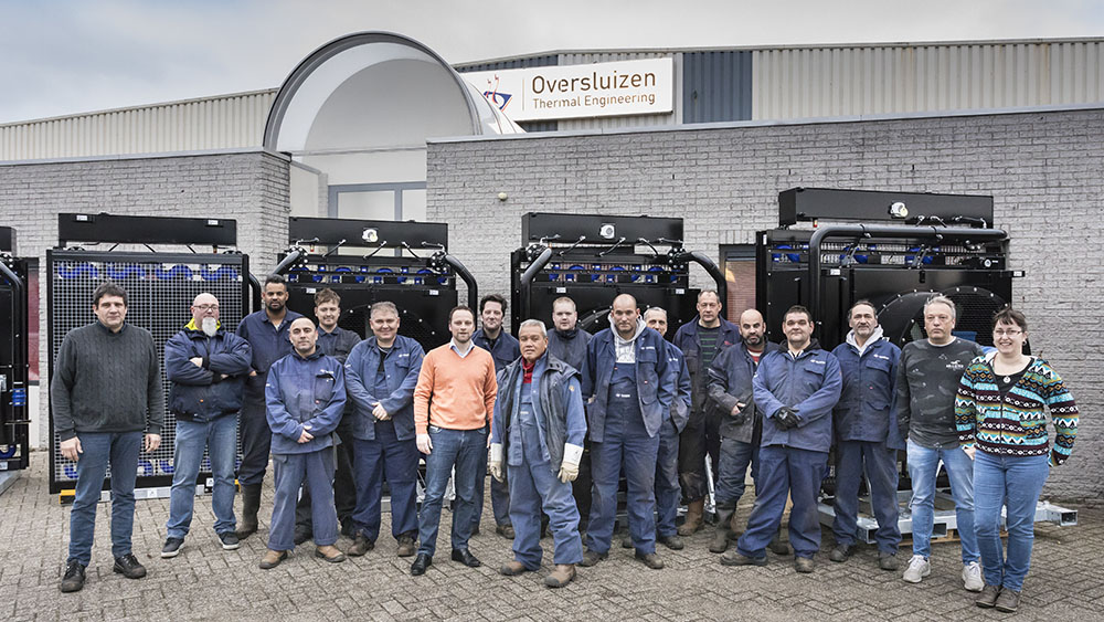
For a project in North America, we were asked to provide an existing vessel with a box-cooled engine with an air cooled solution. The conversion set had to be sent as complete as possible, so that minimal adjustments had to be made on site to realize this conversion.
The complete project consisted of 4 identical vessels
Project data:
- Engine: Caterpillar C32 (EPA Tier3) @1800 rpm.
- Request: Delivery of an air cooled heat exchanger.
- Ambient conditions:
- ambient temperature: -15 °C tot 35 °C
- normaal
- limited space, location outside.
Scope of delivery Oversluizen:
- HT + LT cooler
- hydraulic oil cooling
- gearbox oil cooling
- small floor area
- good service options
- expansion tank HT + LT circuit
- electric fan 480V / 60Hz (2-speed) incl. anti-condensation heating
- piping to agreed location
- integrated measuring points + sensors
Engine data @ 1800 rpm 895kW:
| Engine coolant | LT circuit | ||
|---|---|---|---|
| Heat | 662 kW | Heat | 224 kW |
| Volume flow | 591 l/min | Volume flow | 300 l/min |
| Maximum pressure drop | < 0.50 bar | Maximum pressure drop | < 0.35 bar |
| Maximum coolant temperature @ 35 degrees C ambient | < 95 °C | Maximum coolant temperature @ 35 degrees C ambient | < 52 °C |
Close cooperation
From the start of the project, Oversluizen has been closely involved in the adjustments that were needed. Because there was very limited space available, separate HT and LT coolers were chosen in consultation with the customer. The disadvantage of 2 separate coolers did not outweigh the enormous adjustments that had to be made to the existing vessel to get this done with a single cooler.
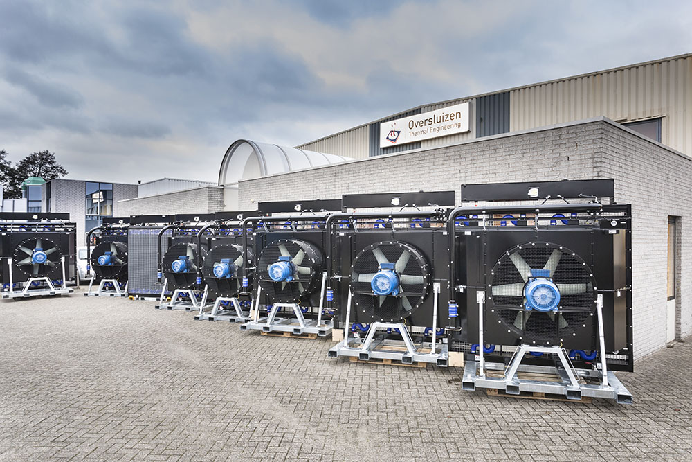
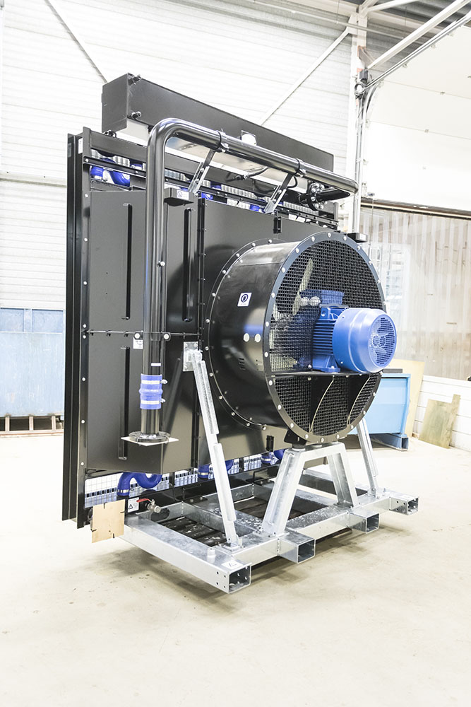
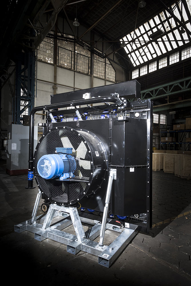
Fan power
Because small cooling surface often results in a higher fan power, this was also an important engineering point. By using 2-speed e-motors, the required electrical power was reduced to <25% of the power in 80% to 90% of the working time.
Only at continuous 100% full load of the C32 engine and temperatures above 25 °C ambient temperature would a high speed be required and this was automatically activated by the PLC by means of the built-in temperature sensors.
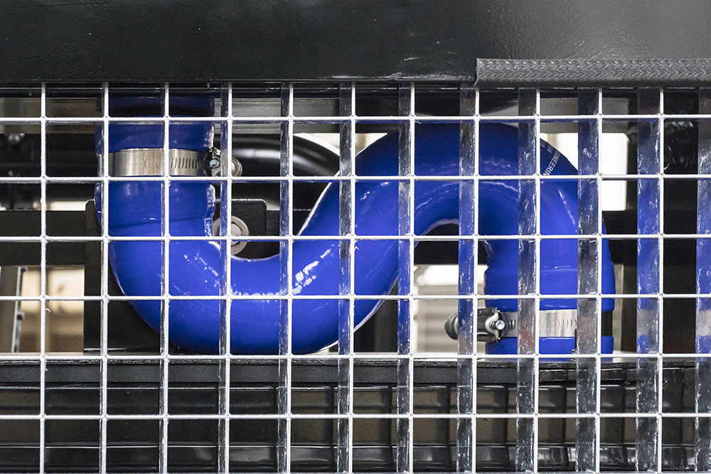
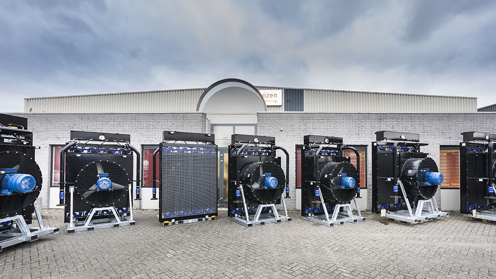
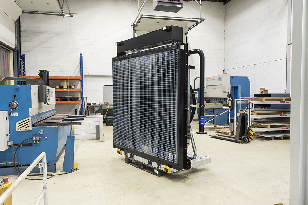
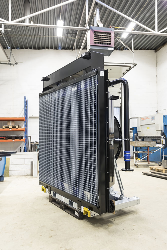
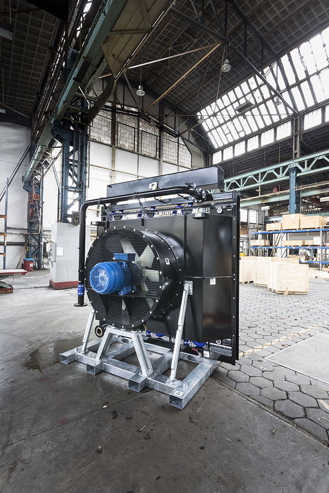
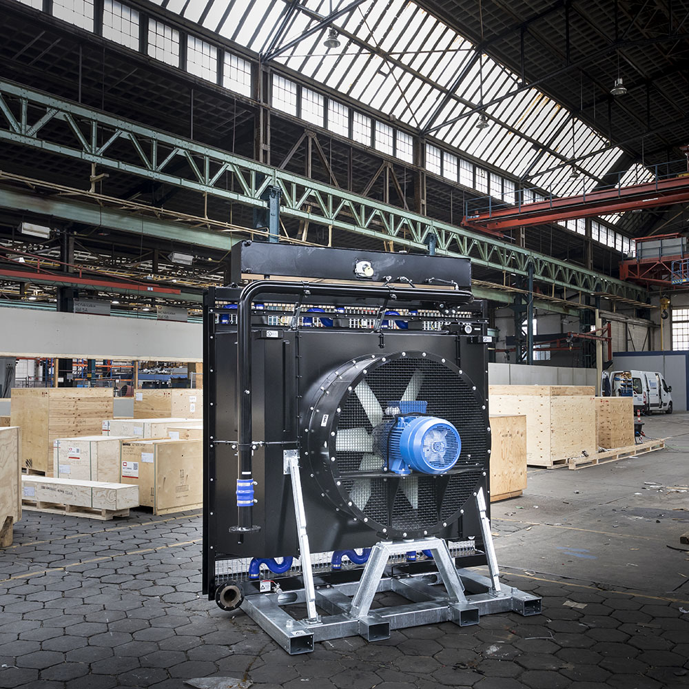
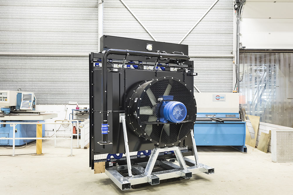
3 Separate coolers including piping
The final design as delivered by Oversluizen, consisted out of 3 separate coolers. Each equipped with a hot-dip galvanized subframe, piping according to agreement, including necessary bellows, hose clamps and expansion tanks.
Both the HT and LT coolers are provided with separate elements to simplify the exchange of coolers if necessary.
- Cooler 1:
- HT cooler
- gearbox cooling
- ventilator: 22 kW at maximum rpm
- Cooler 2:
- LT cooler
- ventilator: 12 kW at maximum rpm
- Cooler 3:
- Hydraulic oil cooler for VG68
- 3,5 kW ventilator at maximum rpm